Projects /
A2FPGA: Five Cards, One Board
A fork of the A2FPGA Multicard Core that adds Videx VideoTerm 80-column card emulation and ThunderClock Plus clock card emulation to a Tang Nano 20K FPGA board — alongside three upstream bus timing bug fixes that had gone unnoticed for two years.
The A2FPGA Multicard Core is an open-source FPGA project that emulates multiple Apple II expansion cards simultaneously from a single physical board — a Tang Nano 20K plugged into one slot of a real Apple II. The upstream project already emulated the Mockingboard, Super Serial Card, SuperSprite, and Disk II. This fork adds two more: the Videx VideoTerm 80-column display card and the ThunderClock Plus real-time clock card.
Both cards are complete, firmware-accurate emulations that pass the same software tests a real card would. CardCat, Apple Pascal, ProDOS, and original Videx demo software all work without modification.

From Composite to HDMI
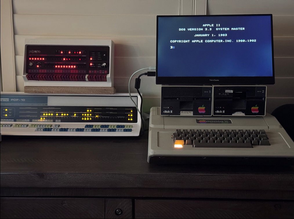
The Apple II+ was designed to display on a television. Its video output is NTSC composite — a signal format optimized for 1970s consumer TVs with low resolution, color bleeding, and scan line artifacts that were considered normal at the time. On a period-correct TV it was fine. On any modern display it looks like what it is: a 45-year-old analog signal from a machine that predates the concept of pixel-accurate display.
The A2FPGA solves this by bypassing composite output entirely. Rather than capturing and upscaling the analog signal, it monitors the Apple II’s video memory directly — the same text pages and hires graphics pages that the Apple II’s video hardware reads — and generates a clean HDMI signal from the raw memory contents. The result is crisp, artifact-free output on any modern monitor, rendered at the correct character and pixel boundaries rather than smeared through an analog chain.
The Videx VideoTerm emulation extends this pipeline. When 80-column mode is active (signaled by the AN0 soft switch), the A2FPGA substitutes its own Videx VRAM rendering for the Apple II’s native 40-column text, producing 80-column output at 640×432 within the 720×480 HDMI frame — sharper than any physical Videx card connected via composite ever looked.
What This Fork Adds
Videx VideoTerm (slot 3) — The MC6845 CRTC, 2 KB video RAM, firmware ROM, 80-column rendering pipeline, 40/80-column switching via AN0, and full Apple Pascal compatibility. The FPGA renders 80-column text at 640×432 within a 720×480 VGA frame, output over HDMI to any modern display.
ThunderClock Plus (slot 1) — Full NEC uPD1990AC serial calendar clock emulation with ProDOS auto-detection. ProDOS finds the ThunderClock signature bytes during boot and installs the firmware’s built-in clock driver automatically — no additional software needed. File timestamps work immediately after boot.
Three upstream bus timing fixes — Discovered during Videx development, these bugs had existed undetected in the upstream codebase for approximately two years: a CPLD bus OE timing error causing ~100ns of bus contention, an Apple ][+ INTC8ROM logic error that permanently breaks all expansion ROM reads after any slot 3 access, and an SSC expansion ROM ownership bug causing bus contention in multi-card builds.
The Hardware
The A2N20v2 board carries a Sipeed Tang Nano 20K module (Gowin GW2AR-18C, 20K LUTs) mounted on a PCB with an Apple II edge connector, a Xilinx XC9572XL CPLD as a bus bridge, SDRAM, and a USB-C connector. The CPLD is the key: it interfaces between the 1MHz Apple II bus and the 54MHz FPGA fabric.
With all five emulated cards enabled (Videx, ThunderClock, SSC, Mockingboard, SuperSprite), the build uses 45 of 46 BSRAM blocks (98%), 6753 of 20736 LUTs (33%), and 4433 of 15552 registers (29%).
Slot Configuration
| Slot | Emulated Card |
|---|---|
| 1 | ThunderClock Plus |
| 2 | Super Serial Card |
| 3 | Videx VideoTerm |
| 4 | Mockingboard |
| 7 | SuperSprite |
The physical A2FPGA card can be installed in any slot. With Videx enabled, slot 3 is recommended since the Videx emulation claims that slot’s address space regardless of where the physical card sits.

HDMI Compatibility
The A2FPGA’s HDMI output works correctly with most flat-panel monitors and TVs after the AVI InfoFrame and control period fixes submitted upstream. One known exception: the Samsung Odyssey Neo G9 does not display the signal directly from the A2FPGA, but works perfectly when an HDMI switch is placed between the A2FPGA and the monitor. The switch appears to recondition the signal electrically, suggesting the Tang Nano 20K’s HDMI output is marginal for strict high-end displays. An HDMI switch is a reliable workaround.